Three-Winding vs Two-Winding Substation Transformers: A Buyer's Comparison Guide
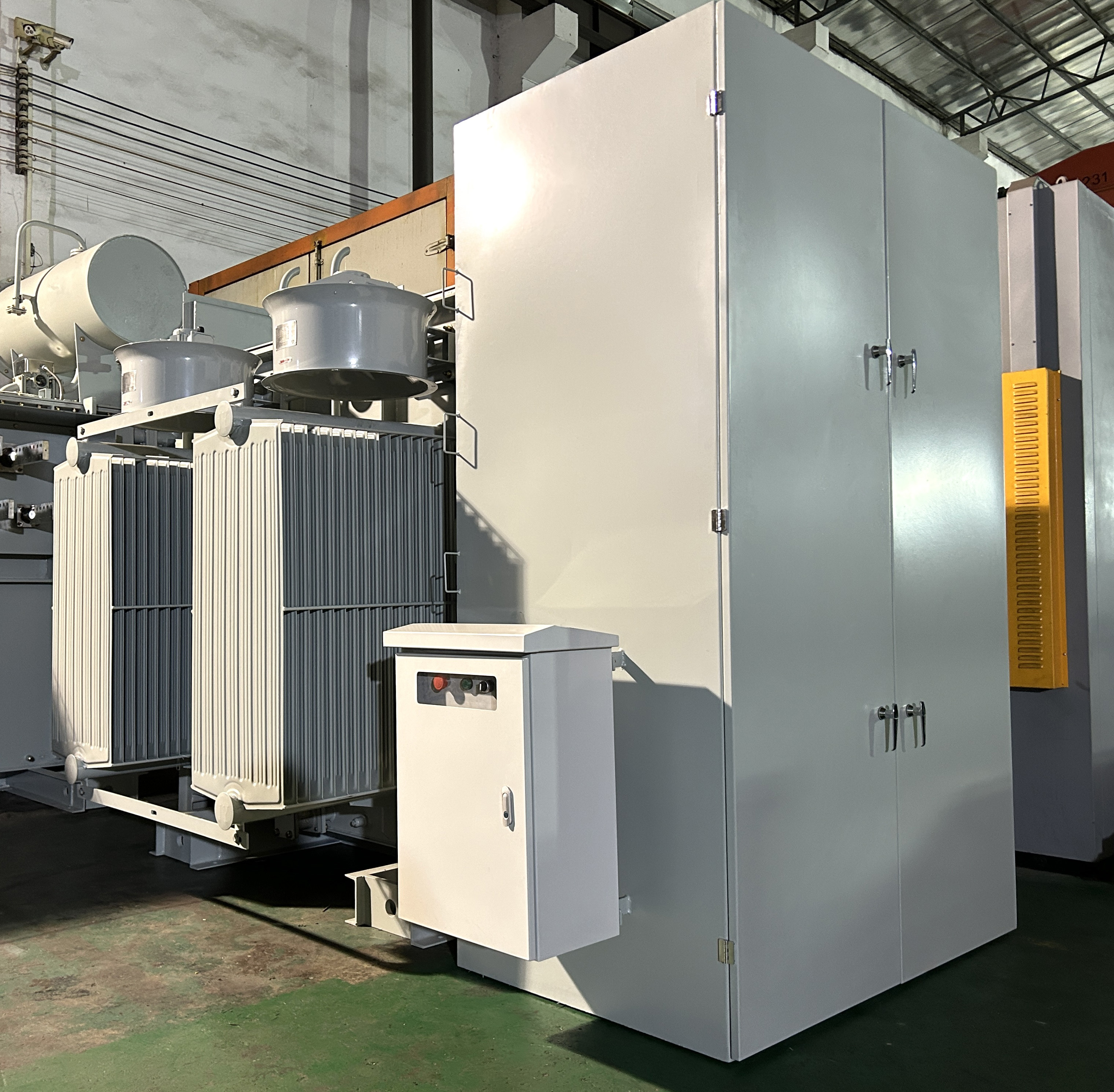
In a brownfield replacement, the choice between a three-winding and a two-winding substation transformer is not settled by the single-line diagram alone. The concrete pad, the bushing heights, the radiator clearances, the cable trench entry points and the transport route already exist, and they limit what the replacement unit can physically be. On retrofit work, winding configuration and tank outline therefore have to be decided as one decision rather than two.
The short answer: a three-winding substation transformer carries a tertiary winding that can supply station auxiliary load or provide a circulating path for third-harmonic current, while a two-winding unit delivers the same primary power transfer with one fewer winding, fewer bushings and a smaller physical envelope. Where the tertiary function is still required by the station design, removing it is not a simplification — it is a change of system function. Where that function has already been migrated elsewhere on site, keeping a third winding can force a larger, heavier and slower unit into a foundation that was never designed for it.
Why the Existing Foundation Usually Decides the Winding Count
New-build substations flow from electrical requirement to civil design. Replacements run the other way: the concrete, the steel and the cable routes are fixed, and the transformer has to be engineered into a space frozen years earlier. The practical question is not which configuration is technically superior in the abstract, but which configuration can be delivered into the available envelope without compromising the guarantees the buyer is paying for.
Six measured constraints normally control that decision:
- Plan dimensions and anchor bolt pattern. Tank length and width, jacking points and the base frame must land on existing anchors, or the pad has to be reworked.
- Overall height and bushing geometry. Phase spacing and bushing centre distances must match the existing conductors, with dielectric clearance to ground and to the structure preserved.
- Dead load and live load on the pad. A third winding typically increases core and coil mass, oil volume and total weight — the foundation may not accept it.
- Radiator and cooling bank keep-out. Cooling banks need free air and service access; a wider radiator arrangement can collide with a firewall, a fence line or the crane approach.
- Cable trench and conduit entries. Low-voltage, control and neutral connections arrive at fixed points that cannot be re-drilled cheaply.
- Transport and rigging envelope. Shipping weight, width and height, plus the road from the port to site, can bind before the foundation does.
Two failure modes recur. In the first, an electrically correct standard unit is ordered and then found not to fit — the cost appears as civil rework, cable re-termination, extended outage and a reworked protection study. In the second, a unit is squeezed into the footprint but the tertiary function, the impedance or the thermal margin is quietly traded away, and the shortfall only surfaces during commissioning or at the first through-fault.
What Is Changing in the North American Supply Picture
Timing has become part of the technical decision. As of Q2 2025, average U.S. power transformer lead times were reported at 128 weeks, and the U.S. Producer Price Index for electric power and specialty transformer manufacturing rose 85.8% between 2019 and 2026, according to Bureau of Labor Statistics data. The global transformer market is estimated to reach USD 88.48 billion by 2030. In parallel, the DOE 2024 final rule for distribution transformers (10 CFR 431.192) sets a compliance date of April 23, 2029, which keeps efficiency specification in scope for every replacement programme.
The commercial implication for a utility, EPC or industrial buyer is direct. When the standard supply route is measured in years, the cost of discovering a footprint conflict after award is no longer a schedule annoyance — it is a lost outage window. That is why the winding decision, the envelope decision and the supplier model are increasingly evaluated together at the front of the project rather than sequentially.
Winley Electric, a transformer manufacturer founded in 2014 and headquartered in Xiamen, China, with manufacturing facilities in Shanghai and Guangdong, publishes a production cycle of 12 weeks for its substation transformers against 80–120 weeks for American manufacturers, and positions cost at 20%–30% lower on comparable scope. Those are the manufacturer's own comparative figures and should be tested against a specific requirement package, but they explain why ODM routes are being examined more seriously for replacement work.
Two-Winding vs Three-Winding: The Engineering Differences That Reach the Purchase Order
What the tertiary winding actually does
A tertiary winding is a third set of windings on the same core. In practice it is specified for one or more of four reasons: supplying station auxiliary load such as cooling, protection and station service; providing a delta path for third-harmonic current so that the harmonic content does not have to be carried by the main windings; supporting reactive compensation or filtering equipment connected at the tertiary voltage; and adding a second utilisation voltage without installing a separate transformer. Each of these is a system function, not a manufacturing preference — which is why the first question in any replacement is whether the function still exists on site.
Where the two designs diverge physically
Adding a winding adds copper or aluminium, insulation, bushings, leads and oil volume. That generally means a larger tank, more radiator surface, greater height and greater mass, and one more set of connections to protect and maintain. The two-winding version of the same MVA rating is normally the smaller and lighter object, and for a footprint-constrained replacement that physical difference is often worth more than any electrical advantage of the third winding.

Protection, impedance and metering consequences
A tertiary changes the zero-sequence paths available to the network, adds a winding whose impedance has to be specified, and introduces additional relay and metering points. For a like-for-like replacement, impedance should be restated on the same MVA base and at the same tap condition as the outgoing unit, otherwise short-circuit duty and protection coordination have to be re-studied. Dropping from three windings to two is not electrically neutral either: the harmonic path and the auxiliary supply must be re-provided somewhere, and that work belongs in the same scope comparison as the transformer quotation.
When the two-winding choice is the better decision
- The tertiary load has already been relocated to a station service transformer or an auxiliary source.
- Third-harmonic management is handled elsewhere in the station design.
- The existing pad, crane access or transport route cannot accept the larger and heavier three-winding unit.
- Fewer bushings, fewer windings and fewer monitoring points are valued over the unused flexibility of a third circuit.
- Loss evaluation favours the simpler magnetic and thermal design for the actual load profile.
Decision summary by winding configuration
| Decision dimension | Two-winding | Three-winding |
|---|---|---|
| Winding and bushing count | Two windings; fewer bushings and leads to protect | Third winding plus additional bushings and leads |
| Station auxiliary supply | Must be provided by a separate source | Can be supplied from the tertiary circuit |
| Third-harmonic path | Handled by the station design elsewhere | Delta tertiary provides a circulating path |
| Physical envelope and weight | Generally smaller and lighter for the same rating | Generally larger tank, more oil and greater mass |
| Retrofit fit to existing pad | Easier to place inside a fixed footprint | More likely to require civil or clearance rework |
| Protection and study effort | Simpler relay and metering set | Extra impedance, relay and metering points to coordinate |
| Maintenance surface | Fewer components to inspect and test | One more circuit to monitor and maintain |
Fitting a New Main Transformer Into an Existing Foundation Footprint
Non-standard outline work is normal ODM territory, but it is bounded. The useful split for a buyer is between the dimensions a manufacturer can legitimately re-arrange and the performance parameters that must not be allowed to drift while the outline is changed.
What an ODM can legitimately change
- Tank length, width and height within dielectric and thermal limits.
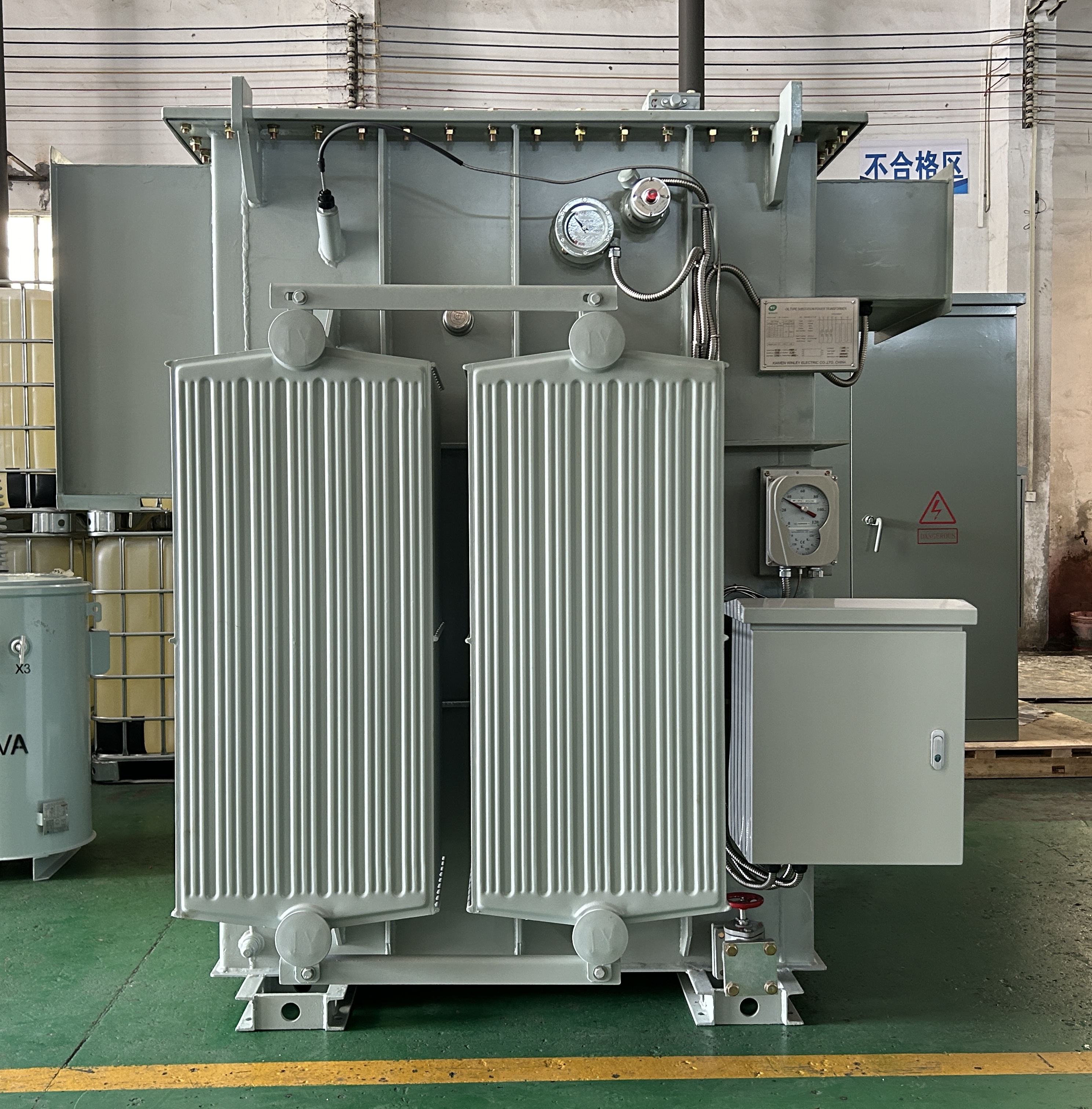
- Radiator bank arrangement and orientation, including removable banks where the transport envelope requires it.
- Bushing orientation, phase spacing and neutral or tertiary bushing placement.
- Base frame, jacking and lifting points, and the anchor bolt pattern that mates with the existing pad.
- Control cabinet position, valve positions, oil filling points and cable entry orientation.
- Accessory selection and drawing design, developed against the customer's measured site data.
Winley Electric supports this work through product selection recommendation, drawing design, accessory selection, acceptance support, transport planning and installation guidance, and its engineering team works to ANSI, IEEE, CSA, DOE2016, NEMA and IEC standards. Manufacturing capability is stated up to 450MVA and 230kV, which covers the voltage classes involved in most North American replacement programmes, including 145kV substation transformer replacements.
What should not become flexible
- Dielectric clearances to ground, between phases and to the structure.
- Guaranteed impedance beyond an agreed tolerance, because protection studies depend on it.
- Temperature rise and thermal margin at the specified ambient and load profile.
- Sound level, which tends to rise when a compact radiator arrangement is forced.
- No-load and load loss guarantees used in the loss evaluation.
- The certification basis — an ANSI standard substation transformer or IEEE standard substation transformer design does not stop being one because the tank outline changed, and the buyer should confirm how a custom outline sits inside the manufacturer's UL and cUL certification scope.
Risk points a buyer must price in
- Thermal margin erosion. Compressing the tank or radiator area to fit a pad removes cooling headroom that cannot be recovered later.
- Impedance drift. Re-arranged windings can shift impedance, which then forces a short-circuit and relay re-study.
- Weight versus foundation. An outline that fits the plan dimensions can still overload the pad or exceed the crane plan.
- Late change control. Changes requested after drawing approval are the most common source of delay in custom-outline work, and both sides should agree in writing when the design is frozen.
- Inspection coverage. Because the design is non-standard, hold points and witness testing matter more than on a catalogue unit.
- Scope comparison. A custom transformer quote looks higher than a catalogue price until civil rework, cable re-termination and outage cost are placed in the same column.
Three retrofit patterns buyers commonly face
Pattern 1 — same winding count, new outline. The lowest-risk retrofit. Winding configuration is retained, and the ODM work is limited to tank outline, radiator arrangement, base frame and bushing placement to match measured as-built conditions.
Pattern 2 — two-winding to three-winding inside the same footprint. The hardest case. The tertiary function has to be added, which pushes against available space, weight and cooling. Buyers should expect to trade something, and the honest trade is usually a revised civil detail rather than a reduced thermal guarantee.
Pattern 3 — three-winding to two-winding with the tertiary duty relocated. Often the most economical route in older stations where the auxiliary load is small and can be served elsewhere. The saving is not only in the transformer but in the reduced bushing, protection and maintenance scope.
A Step-by-Step Retrofit Evaluation Sequence
- Survey the as-built. Measure pad dimensions, anchor pattern, bushing heights, clearances, trench entries, crane approach and road access. Do not design from the original drawing alone.
- Re-confirm the winding requirement with the system owner. Establish in writing whether the tertiary circuit still serves load, harmonic management or future interconnection. This single answer often decides the whole comparison.
- Fix the envelope and weight budget before design begins. State maximum plan dimensions, maximum height, maximum shipping weight and the rigging method as hard input, not aspiration.
- Issue a complete requirement package. Ratings, voltages, taps, impedance and its base, loss evaluation, sound level, ambient and load profile, applicable standards (ANSI, IEEE, CSA, DOE2016, IEC), and the required certification basis.
- Run the ODM drawing and design review. Winley Electric handles selection recommendation, drawing design and accessory selection against the measured data, so the outline is agreed before steel is cut.
- Verify dielectric, thermal and short-circuit performance. Confirm the design basis and the test evidence. Winley's factories include professional type test equipment such as lightning impulse test devices alongside conventional test sets.
- Control the build through hold points. Winley applies mandatory stop points after irreversible processes and before critical performance tests, where authorised quality personnel must inspect and sign off before the next process starts. All products undergo factory inspection in accordance with standard specifications before shipment, and acceptance support is available.
- Plan transport, installation and handover. Transport planning, installation guidance and a two-year free maintenance service form part of Winley's standard support, together with 24/7 technical support.

Where Each Configuration Fits
Application context usually settles the winding question faster than a technical debate. The categories below describe where each configuration is typically the practical choice; they are procurement guidance, not a substitute for the station study.
- Utility substation transformer replacements. Retain the three-winding arrangement when the tertiary still supplies station load or supports harmonic management; move to two-winding only when that duty is formally relocated.
- Industrial parks and heavy industrial bases. Two-winding main power transformer substation designs are common where auxiliary supplies come from separate units, and the smaller envelope simplifies staged replacement.
- New energy power stations. Solar substation transformer applications usually prioritise simple, robust step-up transformation, with auxiliary supply handled separately.
- Data center substation transformers. Redundancy and predictable protection coordination often favour simpler winding arrangements and multiple parallel units over a single complex unit.
- Municipal power distribution networks and distribution transformer substation upgrades. Compact and unit substation transformer arrangements are frequently used where space is tight and the tertiary function is not required at the primary unit.
- Commercial complexes, large buildings and power engineering projects. Where a second utilisation voltage is genuinely needed at one point, a three-winding electrical substation transformer can replace two units and reduce the overall footprint of the installation.

Comparison Table: Sourcing a Replacement Unit
The figures below separate what is independently verified from what is a manufacturer's own comparative claim. Buyers should treat the second category as a starting position to be tested against a specific requirement package.
| Parameter | Winley Electric (stated) | U.S. market reference | Source status |
|---|---|---|---|
| Production cycle | 12 weeks | 80–120 weeks for American manufacturers, per Winley's comparison | Manufacturer comparison claim |
| Cost position | 20%–30% lower on comparable scope | Baseline | Manufacturer comparison claim |
| Average U.S. power transformer lead time | — | 128 weeks as of Q2 2025 | Independent market research, 2025 |
| U.S. transformer producer price trend | — | +85.8% between 2019 and 2026 | U.S. Bureau of Labor Statistics |
| Global transformer market | — | Estimated USD 88.48 billion by 2030 | Market forecast, 2025–2030 |
| Rated manufacturing capability | Up to 450MVA and 230kV | — | Winley Electric company data |
| Standards and certification | ANSI, IEEE, CSA, DOE2016, IEC60076, NEMA; UL and cUL certified; ISO, CE, TUV, EMC | — | Winley Electric company data |
| Warranty and support | 2-year free maintenance; 24/7 technical support | — | Winley Electric company data |
Frequently Asked Questions
Can a footprint-customized three-winding unit still meet ANSI/IEEE and UL requirements?
Yes, provided the customisation stays inside defined design and certification boundaries. A custom tank outline does not change the standard basis of design: Winley Electric manufactures to ANSI, IEEE, CSA, DOE2016 and IEC60076 requirements, and holds UL and cUL certification. Because the outline is non-standard, the buyer should confirm at drawing approval how the specific configuration is covered by that certification, and require factory inspection in accordance with the agreed specification before shipment.
Can an ODM manufacturer change the tank outline to match an existing foundation?
Within limits, yes. Tank dimensions, radiator arrangement, bushing orientation, base frame, anchor pattern and cabinet position can be re-engineered against measured site data. What should not be traded away is dielectric clearance, guaranteed impedance, thermal margin, sound level or loss performance. Winley Electric employs 35 engineers and supports selection recommendation, drawing design and accessory selection, with manufacturing capability up to 450MVA and 230kV.
How should budget be set for a non-standard outline compared with a standard unit?
Compare total installed cost, not transformer price. A custom outline adds engineering and drawing effort, but avoids civil rework, cable re-termination and outage extension. Winley Electric states cost at 20%–30% lower than American manufacturers on comparable scope, and a 12-week production cycle; the correct method is to issue the same fixed requirement package to every bidder and compare like-for-like scope, including accessories, testing, transport and support.
Can the design be validated before the full unit is built?
Validation on a large power transformer is a documentation and inspection process rather than a physical sample. It runs through measured as-built data, drawing and design review, agreed hold points after irreversible processes, and factory inspection against the specification before dispatch. Winley Electric operates mandatory signed hold points, uses type test equipment including lightning impulse test devices, and provides acceptance support and a two-year free maintenance service.
What lead time should be planned for a custom-outline replacement?
Plan two clocks: engineering and production. Winley Electric publishes a 12-week production cycle, against 80–120 weeks stated for American manufacturers, while independent research put average U.S. power transformer lead times at 128 weeks as of Q2 2025. A non-standard outline adds drawing and approval time before production starts, so the envelope and winding decision should be frozen early to protect the slot. To start that review, send measured pad dimensions and the existing nameplate to steven@winley-electric.com or WhatsApp +8618650108051.
Conclusion
The three-winding versus two-winding decision is an electrical question with a physical answer. Where the tertiary circuit still performs work in the station, keeping it is a system requirement, and the ODM task becomes fitting a larger, heavier unit into an existing envelope without eroding thermal or dielectric margin. Where that duty has moved, a two-winding substation transformer usually delivers the same power transfer with a smaller footprint, fewer bushings and a simpler protection scheme.
The disciplined route is consistent in both cases: measure the as-built, confirm the winding function in writing, freeze the envelope and weight budget before design, and treat impedance, thermal margin, sound level and certification as non-negotiable. Suppliers should be compared on total installed cost and on the evidence behind their inspection and certification claims, not on catalogue price alone. Handled that way, an ODM custom outline becomes a controlled engineering decision rather than a construction risk.
Request a Footprint-Fit Review
Send your measured pad dimensions, existing nameplate data and single-line diagram to Winley Electric for a winding-configuration opinion and a quotation on a custom-outline substation transformer.
Email: steven@winley-electric.com | WhatsApp: +8618650108051 | Website: www.winley-electric.com
Click to view more substation power transformer projects from Winley Electric: https://www.winley-electric.com/supplier-4803516-substation-power-transformer
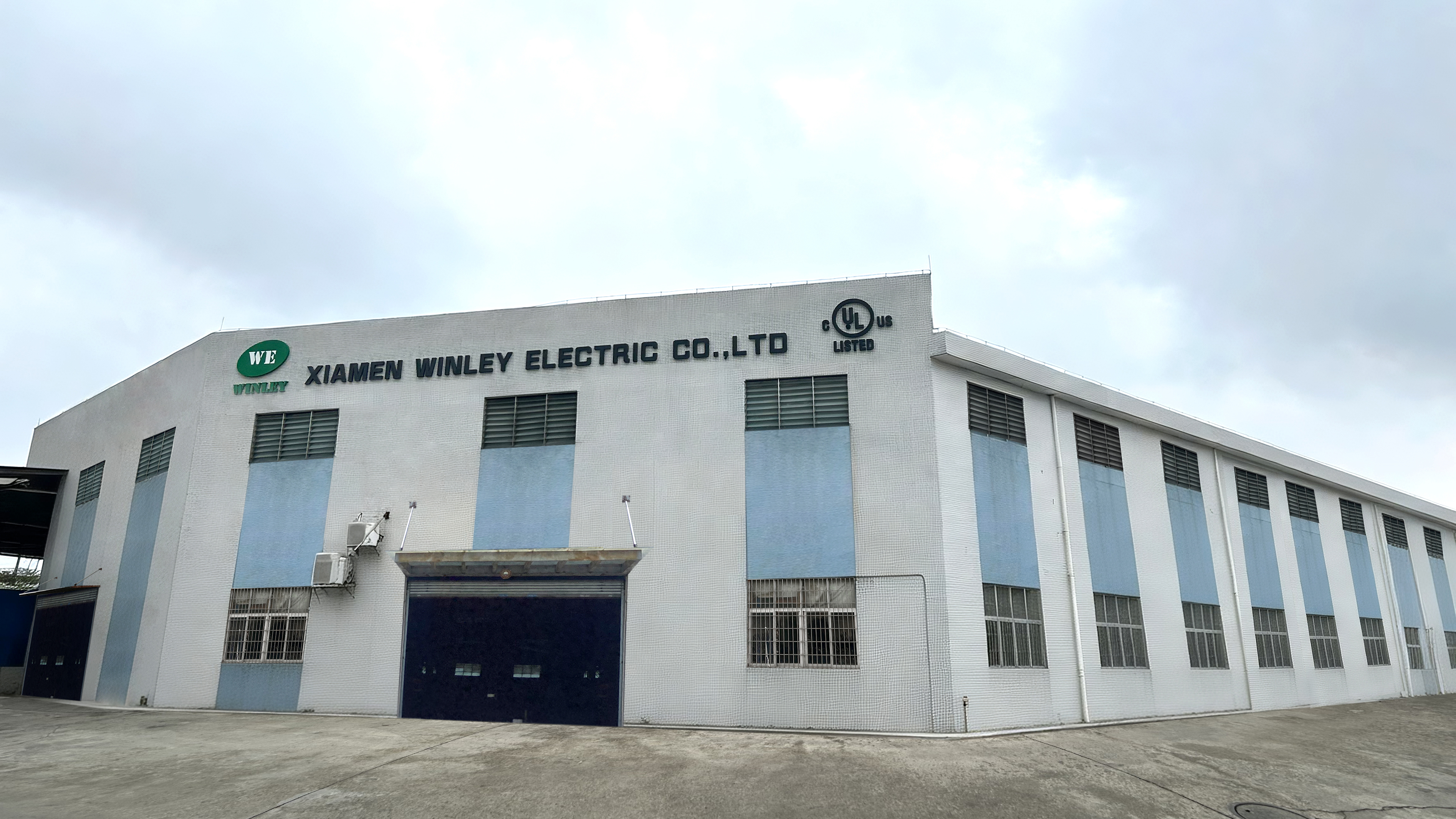
Xiamen Winley Electric Co.,Ltd, No. 99 Yilan Road, Siming, Xiamen, Fujian, China.

Have Questions or Need More Details?
Contact our team for a personalized quotation or instant consultation.
Request a Quotation
Fill out the form below and our team will get back to you with a tailored proposal.
WhatsApp Direct Chat
Prefer to chat in real-time? Message us on WhatsApp for instant assistance & quick answers.
- Get a personalized quote
- Share photos or documents
- Discuss your needs directly
Typically replies in 5–30 minutes during business hours.