Step-Up vs Step-Down Substation Transformers for Renewable Energy Plants in North America
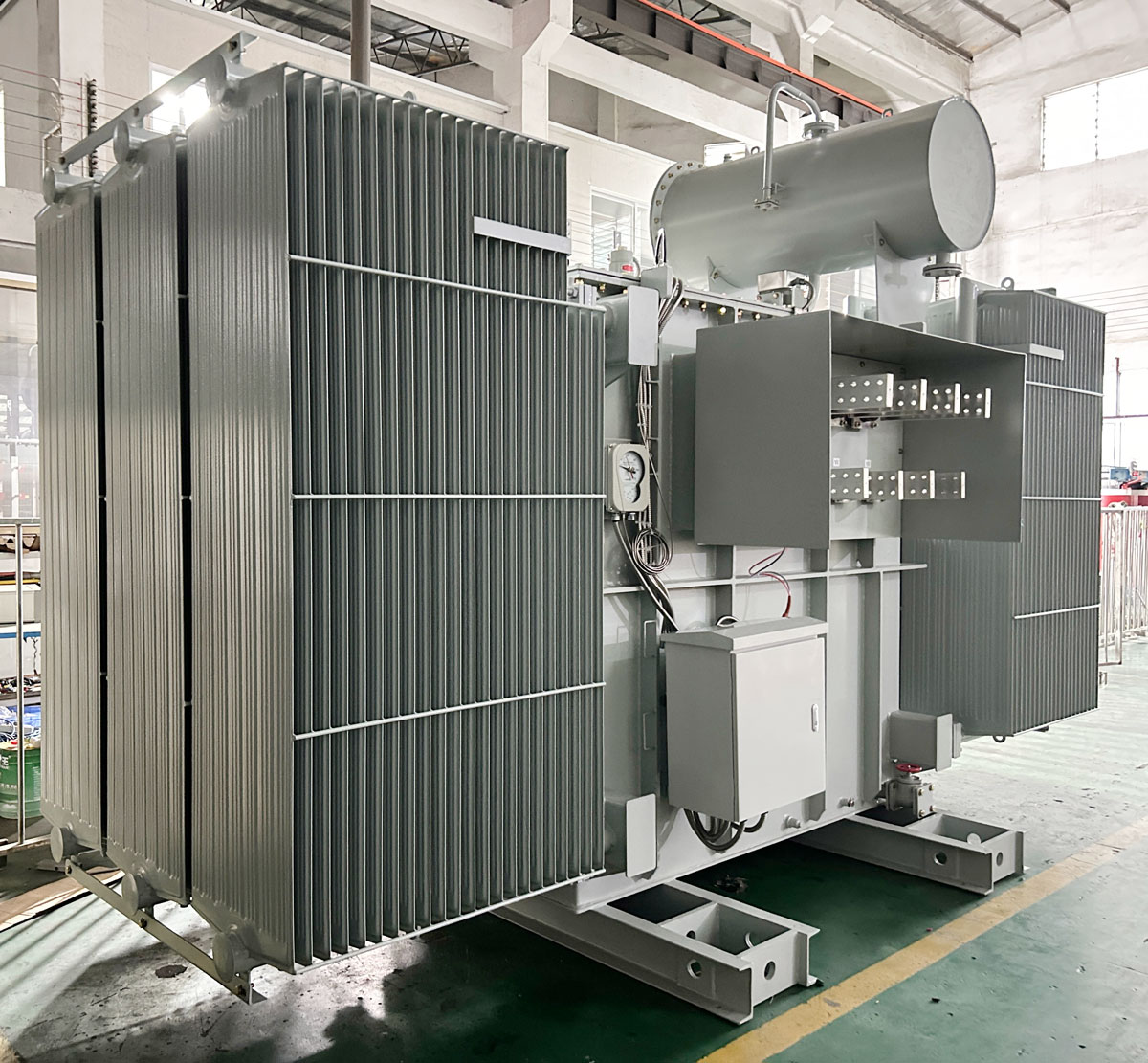
Renewable energy plants in North America rely on substation transformers to connect generation, storage, and site loads to the grid. A substation power transformer is core equipment in medium- and high-voltage power transmission and distribution systems: it converts voltage levels for efficient long-distance power transmission, stabilizes grid voltage, and reliably supplies electricity to residential, commercial, industrial, and large-scale facilities. In a utility-scale solar, wind, or battery storage plant, this function appears in two directions: step-up for power collection and grid interconnection, and step-down for plant auxiliary supply. Understanding the difference affects specification, compliance, and long-term operating performance.
Problem Definition: Why Step-Up and Step-Down Transformers Are Not Interchangeable
Although both step-up and step-down units may be described as substation transformers, they are engineered for different operating conditions and different roles inside a renewable project.
A step-up substation transformer receives power from inverters, wind turbine converters, or battery PCS systems at low voltage and raises that power to a medium- or high-voltage collector or interconnection level. The main technical challenges are fluctuating generation output, converter harmonics, frequent load cycling, and, in storage applications, bidirectional power flow.
A step-down substation transformer performs the opposite role. It takes medium voltage from the plant collector bus and supplies auxiliary loads such as control rooms, lighting, SCADA, HVAC, cooling, and fire-suppression systems at 480 V, 600 V, 208 V, or similar utilization voltages. The main challenges are continuous 24/7 availability, stable voltage, low losses, and reliable grounding.
Procuring the wrong configuration can cause voltage regulation problems, protection relay miscoordination, wasted capacity, and project delays. Buyers at the awareness and research stage should therefore distinguish the two functions before selecting a transformer manufacturer.
Industry Background: North American Grid Modernization and the Growing Demand for Substation Transformers
Verified market data helps explain the importance of careful specification. According to MarketsandMarkets, the global transformer market is estimated at USD 64.64 billion in 2025 and is projected to reach USD 88.48 billion by 2030, driven by grid modernization and rising electricity demand. Global Market Insights values the global substations market at USD 128.5 billion in 2024, with growth to USD 178.9 billion by 2034 at a CAGR of 3.2%. SNS Insider projects the smart transformer market to grow from USD 3.17 billion in 2025 to USD 10.15 billion by 2035 at a CAGR of 12.35%, reflecting the need for real-time grid monitoring.
Insulation technology also matters. Grand View Research reports that oil-immersed transformers held approximately 59.3% of the power transformer segment in 2025 due to cooling efficiency and durability in utility applications. Much of the supply base is concentrated in Asia Pacific, which accounted for about 41.1% of global transformer revenue in 2025. For North American projects, compliance remains a defining factor: substation transformer designs are primarily governed by the IEEE C57 series, while UL 1561 applies to liquid-filled units and UL 1562 applies to dry-type units.
Global high-voltage equipment suppliers such as Hitachi Energy, Siemens Energy, GE Vernova, Eaton, and Schneider Electric dominate the conventional utility supply chain. However, project developers and EPCs increasingly evaluate Chinese OEMs for flexible, specification-driven manufacturing, particularly for renewable applications that require custom voltage packages and project-specific compliance.
Detailed Solution: Winley Electric's Substation Transformer Platform and OEM Capabilities
Xiamen Winley Electric Co., Ltd. (Winley Electric) is a transformer manufacturer established in 2014 and headquartered at No. 99 Yilan Road, Siming, Xiamen, China. The company specializes in manufacturing various types of transformers rated at 145 kV and below, with major markets in North and South America and export business accounting for 70% of total sales. The manufacturing facility covers 45,000 m², employs approximately 220 staff, and has an annual production capacity of 35,000 units.
The main product relevant to renewable plants is the Substation Power Transformer. Winley Electric defines this product as core equipment in medium- and high-voltage power transmission and distribution systems. Capacity ranges from 150 kVA to 100 MVA; primary voltage is typically 2.4 kV to 138 kV; secondary voltage is typically 0.6 kV to 35 kV. Applicable standards include NEMA, ANSI C.57, DOE, and IEEE as required. Typical application scenarios are utility substations and distribution substations, where the transformer stabilizes grid voltage and reliably supplies electricity to residential, commercial, industrial, and large-scale facilities.
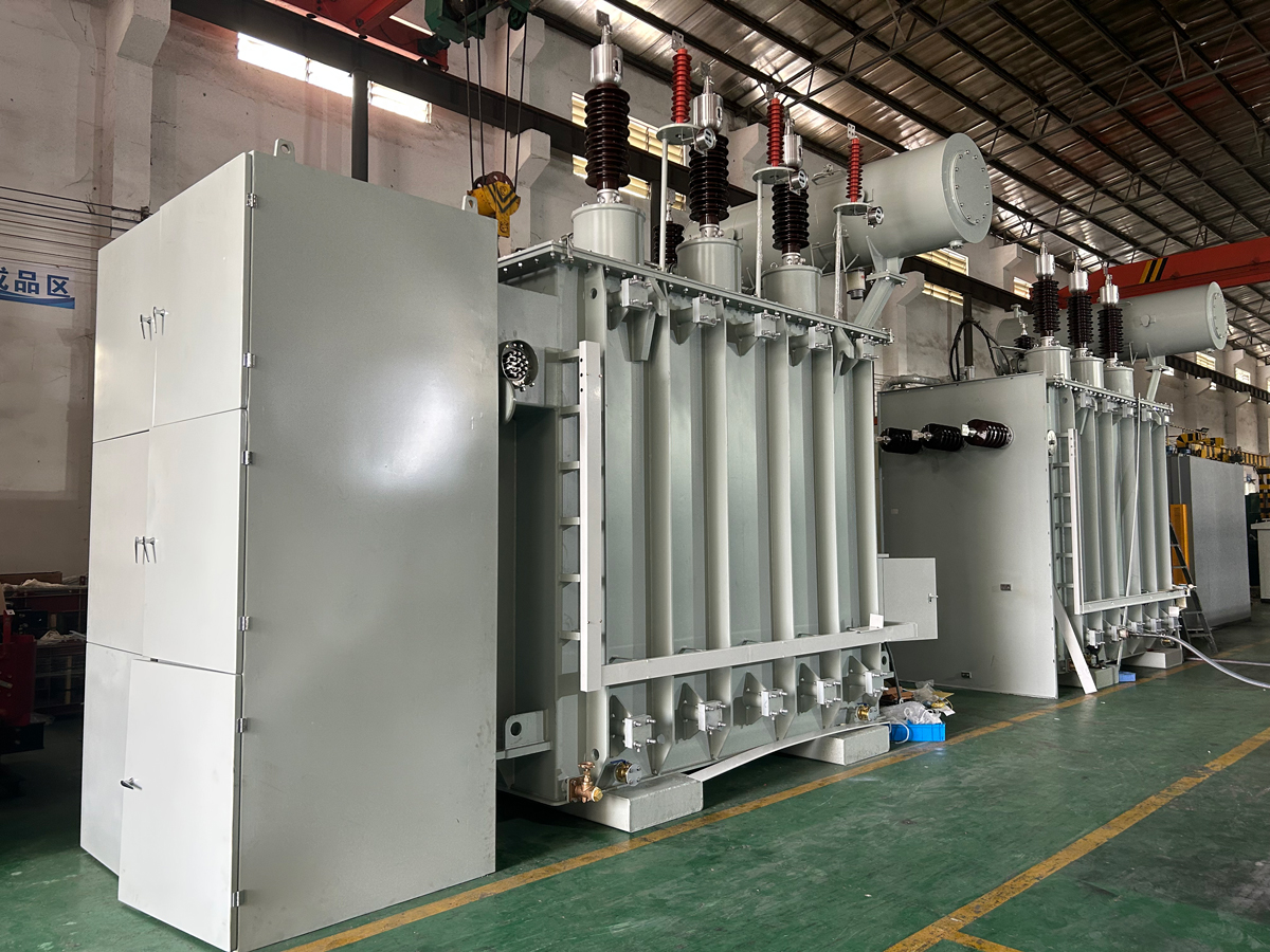
Renewable-Specific Transformer Examples
Winley Electric has produced several configurations that correspond directly to the two voltage directions used in renewable plants:
- Solar and BESS step-up. A 6500 kVA double-split oil-immersed step-up transformer converts dual 480 V PCS outputs to 13.8 kV for solar and battery storage integration. Double-split windings help isolate parallel inverter groups and reduce circulating current.
- Solar farm bidirectional step-up and step-down. A 2500/3100 kVA conservator-type transformer configured for 24.94 kV to 480Y/277 V supports solar farm grid interconnection and can operate in both directions where required.
- Wind farm collector and auxiliary buses. A 10/11.2/12.5/14 MVA multi-capacity dual-voltage transformer serves wind farm collector systems and auxiliary buses, allowing capacity flexibility across project phases.
- Wind dual-bus distribution. A 7500/10000 kVA dual-secondary transformer with MIDEL 7131 ester fluid supports dual-bus wind farm distribution where fire safety and environmental performance are priorities.
- Grid interconnection. A 40 MVA 44 kV to 34.5 kV substation transformer addresses utility-scale renewable grid interconnection at the transmission interface.
Flexible OEM Customization
The R&D team at Winley Electric consists of 35 engineers with experience in ANSI, IEEE, CSA, DOE2016, NEMA, and IEC standards. OEM projects can address customized primary and secondary voltages, tap configurations, impedance, cooling class such as ONAN or ONAF, winding arrangements, tank material, insulating fluid, bushings, and accessories. The company also provides product selection recommendations, drawing design, accessory selection, acceptance support, transportation planning, and installation guidance.
From a quality-assurance standpoint, Winley Electric follows an ISO 9001-based production management system, operates a transformer material traceability system and supplier evaluation mechanism, and uses professional type-test equipment such as lightning impulse test devices. Products are certified under UL and cUL, and the company can open UL partner authorization for customers based on actual need. A 2-year free maintenance service is included, and 24/7 technical support is available.
Step-by-Step Breakdown: How to Specify an OEM Substation Transformer for a Renewable Project
The following framework helps project teams translate a renewable plant architecture into a complete transformer specification:
- Define the voltage architecture. Identify the inverter or converter output voltage, collector voltage, transmission or interconnection voltage, and auxiliary load voltage. For example, a solar block may operate at 480 V, collect at 34.5 kV, and interconnect at a higher transmission voltage.
- Determine the transformer role. Assign step-up duty for generation-to-grid power flow and step-down duty for station service. Some units, such as a 24.94 kV to 480Y/277 V bidirectional transformer, may perform both functions in storage applications.
- Select capacity and cooling. Match the MVA rating to the plant block size and ambient conditions. Oil-immersed substation transformers dominate utility renewable applications because of cooling efficiency and durability; ONAF fan-assisted cooling can extend capacity.
- Choose tap and voltage regulation strategy. Decide between off-circuit taps for predictable voltage levels and on-load tap changers for variable grid conditions. Multi-step tap configurations may be required for fast-changing renewable loads.
- Select insulating fluid. Mineral oil, natural ester such as FR3, or synthetic ester such as MIDEL 7131 affects fire safety, environmental risk, and enclosure design. Ester fluids are increasingly specified for wind and solar sites with stringent environmental requirements.
- Design the tank and enclosure. Carbon steel tanks suit most utility sites; 304 stainless steel tanks provide corrosion resistance for coastal plants and harsh environments. Conservator tanks support thermal expansion and preserve dielectric strength.
- Confirm compliance and certification. Verify IEEE C57, ANSI C.57, DOE2016, NEMA, and CSA requirements. Liquid-filled units may require UL 1561 listing depending on project jurisdiction.
- Plan testing, logistics, and installation. Request routine factory tests, type tests such as lightning impulse, acceptance support, transportation planning, and installation guidance from the manufacturer.
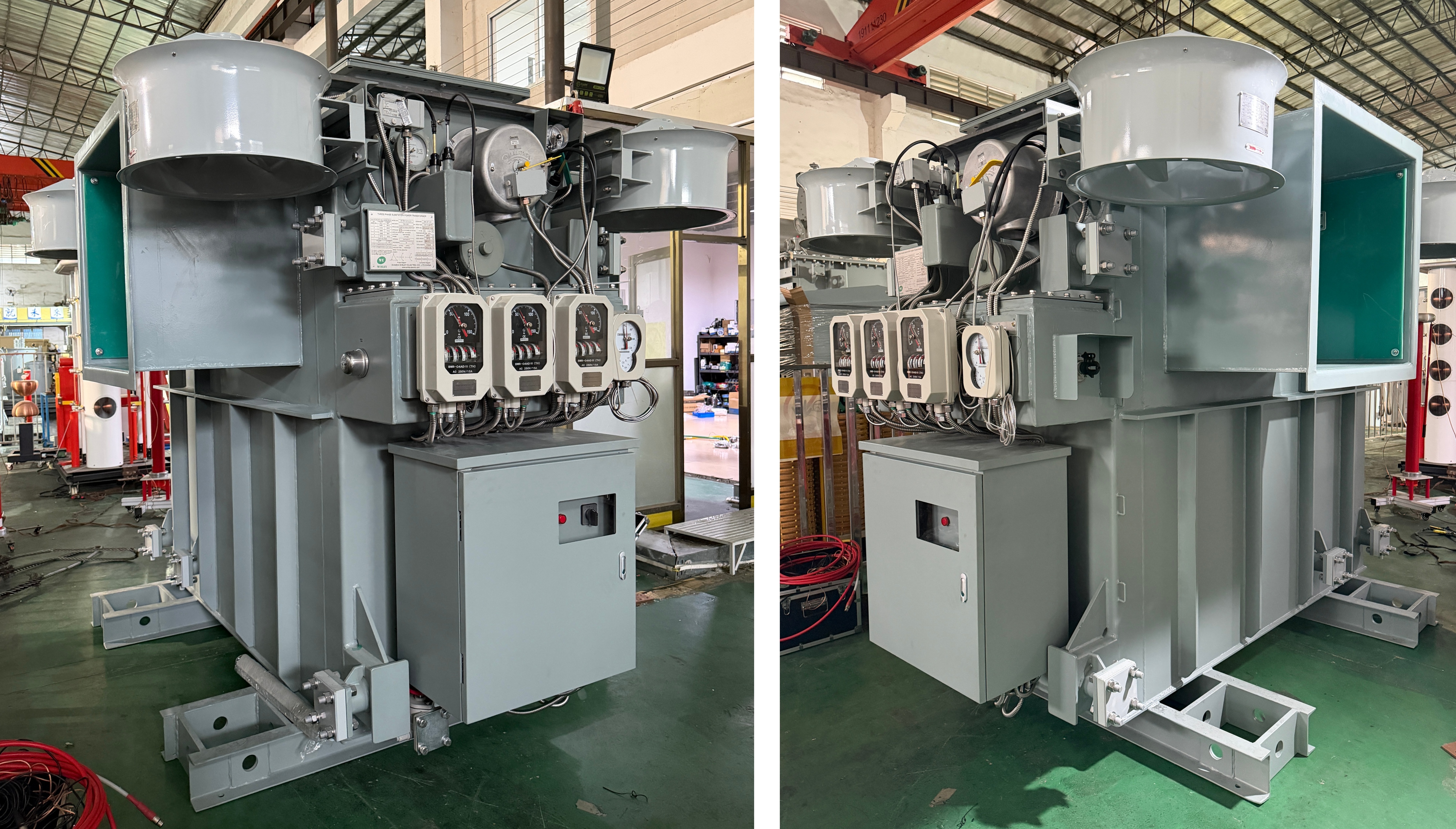
Use Cases: Solar, Wind, and Energy Storage Plants
Utility-Scale Solar Farms
In a utility-scale solar plant, the main step-up function can be handled by a large substation transformer at the point of interconnection, while smaller station-service transformers step down collector voltage for plant auxiliaries. Winley Electric's double-split solar transformer, rated at 6500 kVA with 480 V to 13.8 kV conversion, is an example of collector step-up design for large solar blocks. On the auxiliary side, a 2500/3100 kVA conservator-type bidirectional transformer at 24.94 kV to 480Y/277 V supports site loads and grid interconnection.
Onshore Wind Farms
Wind farms require transformers at the turbine and at the substation. At the substation level, a 10/11.2/12.5/14 MVA multi-capacity dual-voltage transformer can serve both wind farm collector and auxiliary buses, giving operators flexibility as turbine capacity is added. For dual-bus layouts, a 7500/10000 kVA dual-secondary transformer with MIDEL 7131 ester fluid separates two independent distribution buses while maintaining fire safety in remote or environmentally sensitive areas.
Battery Energy Storage Systems (BESS)
BESS projects add a distinctive requirement: bidirectional power flow. The same transformer must step up PCS output to the grid during discharge and step down grid power to charge the battery. Configurations such as the 8 MVA dual-split-winding substation transformer with 34.5 kV on the primary and dual 480 V secondaries support utility-scale storage integration. A 40 MVA 44 kV to 34.5 kV substation transformer can also serve transmission-connected BESS interconnection where the storage plant connects at a sub-transmission voltage.
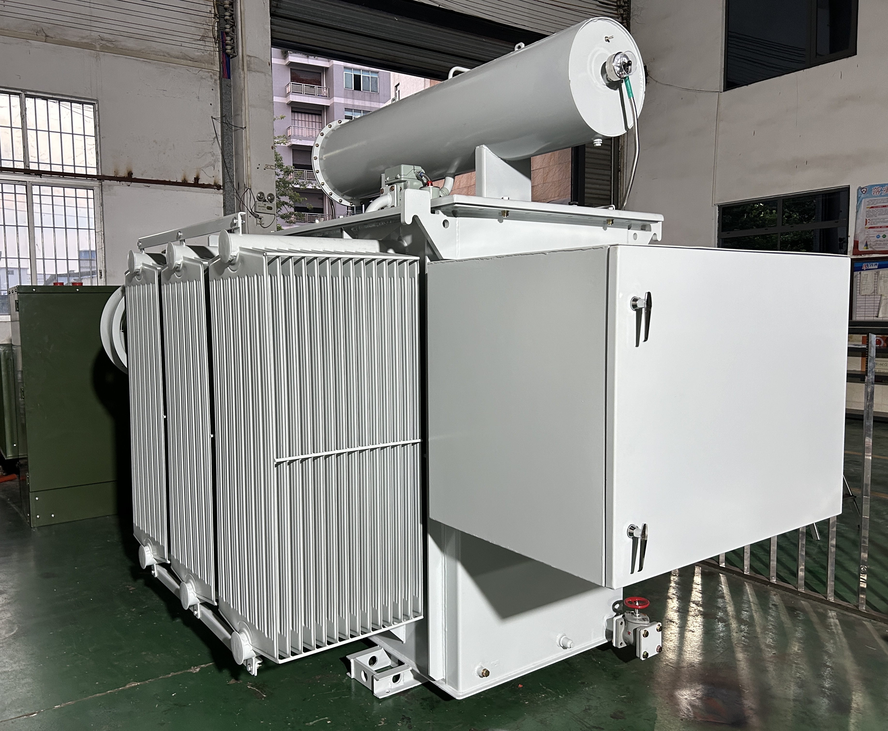
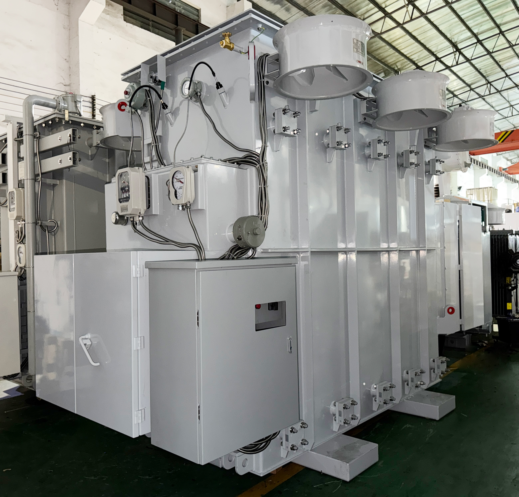
Comparison Table: Step-Up vs Step-Down Substation Transformers in Renewable Plants
| Comparison Criterion | Step-Up (Power Collection / Interconnection) | Step-Down (Station / Plant Auxiliary) |
|---|---|---|
| Primary function | Raises generation or PCS voltage to collector or grid interconnection voltage | Lowers collector voltage to utilization voltage for site loads |
| Typical voltage direction | 480 V/600 V/800 V to 13.8 kV, 24.94 kV, or 34.5 kV; or collector voltage to transmission voltage | 12.47 kV, 24.94 kV, or 34.5 kV to 480 V, 600 V, 208 V, or 415 V |
| Load pattern | Intermittent, generation-dependent, frequent cycling | Continuous 24/7 operation, relatively stable load |
| Design priorities | Harmonic tolerance, short-circuit withstand, reverse power flow capability | Voltage stability, low losses, reliability, low noise |
| Typical winding arrangement | Double-split windings or multi-windings for multiple inverter or PCS groups | Dual-secondary or single secondary for separate auxiliary buses |
| Winley example | 6500 kVA double-split transformer, 480 V to 13.8 kV, for solar and BESS | 2500/3100 kVA bidirectional transformer, 24.94 kV to 480Y/277 V |
FAQ
Which standards govern step-up and step-down substation transformers for North American renewable projects?
For the North American market, substation transformer designs are primarily governed by the IEEE C57 series; UL 1561 applies to liquid-filled transformers and UL 1562 to dry-type units. Winley Electric produces transformers that comply with ANSI, IEEE, CSA, DOE2016, and IEC60076 as applicable, with UL/cUL certification available. The substation power transformer range covers capacities from 150 kVA to 100 MVA, primary voltages from 2.4 kV to 138 kV, and secondary voltages from 0.6 kV to 35 kV.
Can Winley Electric custom-build both step-up and step-down substation transformers for solar, wind, and storage plants?
Yes. Winley Electric's R&D team includes 35 engineers with experience in ANSI, IEEE, CSA, DOE2016, NEMA, and IEC standards. The company has built renewable-specific units such as a 6500 kVA double-split solar step-up transformer from 480 V to 13.8 kV, a 2500/3100 kVA bidirectional transformer from 24.94 kV to 480Y/277 V, and a 10/11.2/12.5/14 MVA dual-voltage transformer for wind farm collector and auxiliary buses. Custom options include dual-split windings, dual secondary windings, ester fluid, conservator tanks, stainless steel enclosures, and on-load tap changers.
How does OEM customization affect the cost of a substation transformer for a renewable project?
OEM transformer cost depends primarily on capacity, voltage class, cooling system, tank material, insulating fluid, and certification requirements rather than a fixed catalog price. Winley Electric helps buyers manage cost through product selection, drawing design, and accessory selection during the engineering stage. Because exports account for 70% of total sales and North and South America are major markets, cost-effective solutions are designed around project-specific requirements. A budget estimate can be confirmed after the technical specification is shared.
Can buyers verify Winley Electric's transformer quality before full production?
Winley Electric operates under an ISO 9001-based production management system with a transformer material traceability system and supplier evaluation mechanism. In addition to routine testing, the factory uses professional type-test equipment such as lightning impulse test devices, and all products undergo strict factory inspection according to standard specifications before shipment. The company also provides a 2-year free maintenance service. Buyers can request product selection recommendations, drawing design, acceptance support, and installation guidance as part of the pre-production process.
What lead time should be planned for an OEM substation transformer project from Winley Electric?
Lead time depends on capacity, voltage class, accessory choices, and certification scope. Winley Electric states that it ensures high-quality delivery of products within the agreed delivery period, supported by advanced production equipment and a mature technical team. To plan a project schedule, share the electrical specification and site requirements with the Winley Electric team for a project-specific delivery plan and transportation arrangement. For sample, quote, or inquiry, contact steven@winley-electric.com or phone/WhatsApp +86-18650108051.
Conclusion
Step-up and step-down substation transformers are both essential in North American renewable energy plants, but they are not interchangeable. Step-up units manage fluctuating generation, harmonics, and reverse power flow; step-down units provide stable, reliable auxiliary power. Winley Electric's Substation Power Transformer range, combined with OEM engineering, allows project teams to specify capacity from 150 kVA to 100 MVA, primary voltages from 2.4 kV to 138 kV, and secondary voltages from 0.6 kV to 35 kV with the required North American compliance.
For project-specific transformer selection, OEM customization, or a proposal, contact Winley Electric at steven@winley-electric.com, phone +86-18650108051, or WhatsApp +86-18650108051. A 24/7 technical support team is available to support drawing design, acceptance, transportation, and installation.
Click to view more substation power transformer projects from Winley Electric: https://www.winley-electric.com/supplier-4803516-substation-power-transformer
Have Questions or Need More Details?
Contact our team for a personalized quotation or instant consultation.
Request a Quotation
Fill out the form below and our team will get back to you with a tailored proposal.
WhatsApp Direct Chat
Prefer to chat in real-time? Message us on WhatsApp for instant assistance & quick answers.
- Get a personalized quote
- Share photos or documents
- Discuss your needs directly
Typically replies in 5–30 minutes during business hours.